

PodPi Volume 12 - Updates
"To the Lighthouse" - Volume 12 introduces a new character call Redd. Redd has the unique power to send and receive infrared signals. In this volume you will learn how two devices can communicate using infrared signals just like your home remote controls.
V12 is the the most complex volume in the PodPi series. Unfortunately some errors were discovered after printing the first edition. Use this guide to find all the updates, get the latest code, correct circuits diagrams and additional information not available in the comic book format.
Overview
Volume 12 introduces multiple concepts that are popular in the maker movement, such as programming your own microcontroller, communicating with other systems as well as sending and receiving infrared messages.img

ATtiny Microcontoller
The Arduino board is powered by an ATMega328 chip from Microchip (formerly Atmel). Microchip manufactures several chips in the same family, from more powerful 32-bit chips to tiny 8-bit microcontrollers. Volume 12 will focus on the ATtiny series - a set of versatile 8 bit microcontrollers. These can be handy in many situations from controlling an LED to more complex tasks.img
Check out page 7 for some examples. Volume 12 comes with two ATtiny84 microcontrollers that you will learn to program. By using this guide, you will be on your way to understand how to upload code. You can then find other examples online and have much fun making cool stuff.
Page 9 - Setup your computer
All ATtiny microcontrollers can be programmed using a special hardware device called a programmer (google "ISP Programmer" for more information). However, the good news is that you can also use your own Arduino board to program these little chips with a handy trick (supported by Arduino).
Before you can use your Arduino board to program the chips, you have to setup your computer (only once) and then your Arduino board (each time you want to use it as an ISP programmer).
Make sure to follow all the steps on pages 9 and 10
- Page 9 - Install the Arduino libraries and code necessary for the ATTiny84. This step is usually only done once per computer. Once installed, the libraries will be available to use each time.
- Page 10 - Configure your Arduino board to become an ISP programmer. During the PodPi series, your Arduino board was configured with the Firmata sketch in order to interface with Johnny-Five. Each time you want to program a ATtiny microcontroller you will have to upload the ISP sketch to transform your Arduino board into a programmer. Each time you want to use Johnny-Five, you will have to upload the Firmata sketch again.
If you intent to program small microcontrollers often, you may want to invest into a dedicated Arduino board or a hardware ISP programmer. They can be found on Adafruit, Amazon or eBay

Page 13 The ATtiny84
Refer to this diagram to wire the ATTiny chip. You are going to control two separate LEDs in this lesson as well as connecting the chip to your Arduino (in ISP programmer mode), ready for programming.
The diagram on the right has been updated from the print version with the correct pin numbers. The pins numbers in ( ) represent the Arduino compatible notation when using commands such as
digitalWrite(pinNumber,HIGH);
In this case, the 'pinNumber' reference can be changed with the actual pin number to control this particular output (like you did with JavaScript all along).
Once you completed the wiring a seen here, go on to the next step and write the code to download to the ATtiny chip.
Remember: You will now code using the C language and not the JavaScript language! C will not work with Johnny-Five.
Page 16 Coding for your ATtiny84
It is time to write some simple code to blink the two LEDs, and upload the code to the chip. Once uploaded, the chip can run on its own - you could disconnect the power from the Arduino and power it from the battery pack.
Use the updated code below:
// the setup function will only run once
void setup() {
  // initialize digital pin 13 as an output.
  pinMode(0, OUTPUT);
  pinMode(2, OUTPUT);
}
// the loop function runs over and over again forever
void loop() {
  digitalWrite(0, HIGH);   // turn the LED on (HIGH is the voltage level)
  digitalWrite(2, LOW);    // turn the LED on (HIGH is the voltage level)
  delay(100);              // wait for a second
  digitalWrite(0, LOW);    // turn the LED off by making the voltage LOW
  digitalWrite(2, HIGH);   // turn the LED off by making the voltage LOW
  delay(300);              // wait for a second
}
Once you completed the code, follow the steps at the bottom of page 16 to upload the code. Make sure to:

Updated Page 16
- Choose the right device - ATtiny 24/44/84
- Choose the 8MHz Internal speed (if you choose 8MHz External you will brick the chip and NOT be able to program it anymore).
- Burn the bootloader
- Upload your sketch
Make sure there are no errors after uploading the sketch. Your two LEDs should now blink. If you need help - don't hesiatet to contact us.
Pages 18, 19 - C Commands
Programming in C is much more difficult that JavaScript. But the language executes faster and is much more efficient. Most microcontrollers are programmed in C. Arduino provides a library with a set of helper functions that abstract a lot of the complexity in programming these chips. For example, the two functions listed on pages 18 and 19 provide a easy way to configure your pins without having to understand the underlying registers and internal functions.

Updated page 19
- pinMode(pin,mode) - This function is used to set the direction of the pin as INPUT or OUTPUT. Input is used to read data from sensors or to receive data from another system. Output is used to send data or to control a device like an LED. Sending a signal to light up an LED.
- digitalWrite(pin,state) - This function is used to send a signal to a particular pin. A digital state can be either HIGH (5V) or LOW (0V).
Refer to our previous diagram for the Arduino pin numbers corresponding to the physical pin numbers on the chip. For example, physical pin #5 (PB2) is actually Arduino compatible pin 2. To light up an LED connected to physical pin 5, you will write the following line:
digitalWrite(2,HIGH);
You may be confused at this stage, and this is why we provided the chart previously as a reference.

The USB Bridge
The USB bridge is a small device that allows you to send serial data (serial protocol) or receive serial data and display it on your computer using a special terminal emulator (like the Arduino Serial Monitor or Putty.exe on PC). The Mac OS has a special command called "screen" that can be called directly from the Terminal window.
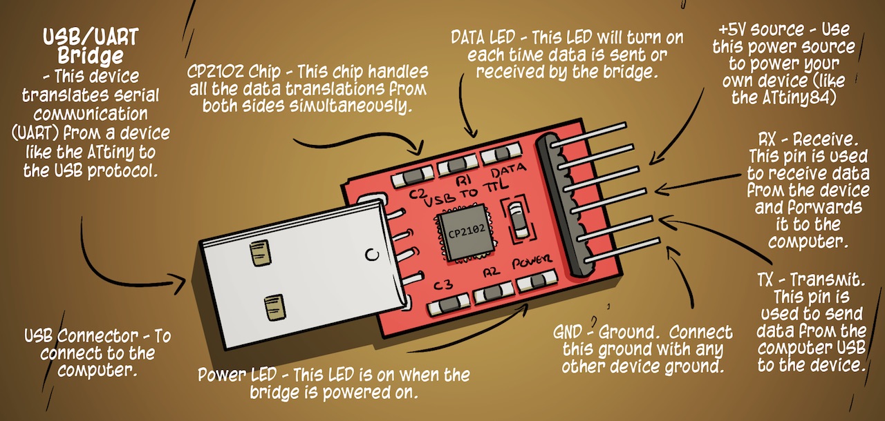
Updated USB Bridge from Page 25
We are going to use two pins from this USB bridge as follow:
- GND - the ground. Serial communications need a common ground to reduce noises and errors. Make sure to connect both GND and not any other pins. You may damage your Arduino or the USB bridge if connected wrong.
- RX - RX stands for Receive Transmission and is used to receive serial data from another device (the ATtiny84 in our case).
Calibrating your ATtiny84
All microcontrollers use a clock (a generated frequency) to process their instructions at a certain speed. The AT series of chips provide an internal clock of 1MHz and 8MHz. This internal clock is not very precise and while it is good enough for most simple projects, it can cause issues when running communication protocols that rely on accurate timings.
Fortunately, these chips provide a calibration method that we can use to adjust the internal clock speed to our needs. In this section, we are going to send a certain string of data to our computer by varying the internal clock until the data received is correct.

Updated Page 27 circuit
To calibrate the chip, you need to set the OSCCAL register to the correct value for your environment (the ambient temperature can influence the internal timing of the chip).
Use the updated circuit here instead of the printed version. Use the code from the printed version and upload it to the chip.